This is a tutorial to build a digital dice: press a button an a random number between 1 and 6 is show using LED in a pattern known from the physical dice.
It is split up in the following steps:
- Let there be LED-Light: Connect an LED (no programming involved, just wiring up).
- Making the LED blink: programming a simple sketch to make the LED blink
- Press a button to start the blinking
- Assembling the Dice pattern
- (digitally) Throwing the Dice
For those who do not know, Arduino is an open-source electronics platform based on easy-to-use hardware and software. It’s intended for anyone making interactive projects. Learn more
What you need
| Description | Quality | |
|---|---|---|
 | Arduino board + USB connector | 1 |
 | Breadboard | 1 |
 | LED | 7 |
 | Resistor (~270 Ohm) | 8 |
 | Button | 1 |
 | Connection wires | 12 |
Set-up
- Arduino Software: To write sketch files and upload them to your Arduino, install the Arduino IDE. See: https://www.arduino.cc/en/software
- Drivers: in case you have a Chinese Arduino-replica with the CG340 chipset, you need an additional driver to communicate with the device. See: http://www.wch-ic.com/downloads/CH341SER_ZIP.html
1 – Let there be LED-Light
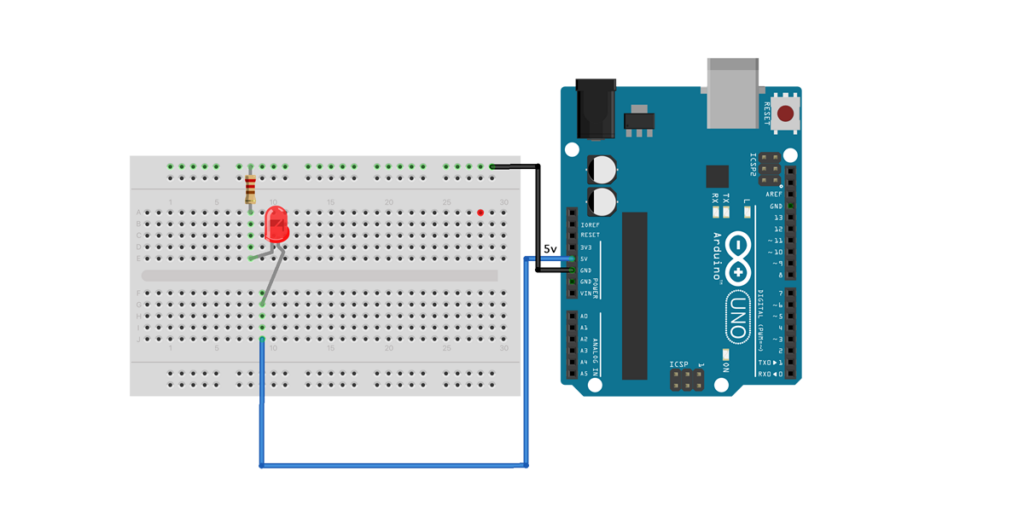
As a first step, we will simple connect a LED to the voltage output of the board. See the schema below. Note that more that 20mA most likely will destroy your LED. An Arduino pin should not exceed 40 mA . To reduce the current flowing through the LED a resistor is placed in series. In this board I have used 270 Ohm. To check the value of your resistor, you can check the colour code on various sides, e.g. here

| Download the supporting material for step 1 in PDF |
2 – Making the LED blink

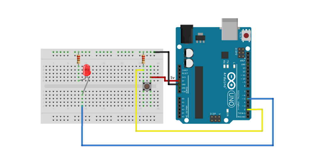
To make it slightly more interesting, in this example we are trying to make the LED blink. For this, instead of connecting the LED with the 5 Volt output, we connect it with PORT 5 and load a small sketch; A sketch is the name that Arduino uses for a program. It’s the unit of code that is uploaded to and run on an Arduino board.
If this is your first sketch, on arduinogetstarted.com you find a good overview and introduction
/*
Arduino Dice - step 1: one LED
Created 27 Mar 2022
By Fred Voorhorst
See: www.educati.ch
This example code is in the public domain.
*/

int LED1 = 5;

#define DEBUG 1

void setLED(int value) {
digitalWrite(LED1, value);
}

void blinkLED(int x){
// blinking the led an x amount of time
for (int i=1; i=x; i++) {
  setLED(HIGH);
  delay(250);
  setLED(LOW);
  delay(250);
}
}
void setup() {
// put your setup code here, to run once:
// set all LED pins to OUTPUT
pinMode(LED1, OUTPUT);

// if we're debugging, connect to serial
#ifdef DEBUG
  Serial.begin(9600);
#endif

//All leds off
  delay(100);
  setLED(HIGH);
  delay(100);
  setLED(LOW);
}
void loop() {
// put your main code here, to run repeatedly:
  blinkLED(5);
  delay(1000);
}
| Download the supporting material for step 2 in PDF |
3 – Press a button to start the blinking

Following the schema above, connect a button to port 2. See here for more information about the issues involved.
/*
Arduino Dice - step 2: one LED + one BUTTON
 Created 27 Mar 2022
 By Fred Voorhorst
 See: www.educati.ch

 This example code is in the public domain.

*/

int BUTTON = 2;
int LED1 = 5;


#define DEBUG 1


void setLED(int value) {
  digitalWrite(LED1, value);
}

void blinkLED(int x){
// blinking the led an x amount of time
  for (int i=1; i<=x; i++) {
    setLED(HIGH);
    delay(250);
    setLED(LOW);
    delay(250);
  }
}


void setup() {
  // put your setup code here, to run once:
  // set all LED pins to OUTPUT
  pinMode(LED1, OUTPUT);

  // set buttin pin to INPUT
  pinMode(BUTTON, INPUT);

  // if we're debugging, connect to serial
  #ifdef DEBUG
    Serial.begin(9600);
  #endif

   //All leds off
  delay(100);
  setLED(HIGH);
  delay(100);
  setLED(LOW);
}

void loop() {
  // put your main code here, to run repeatedly:

  int p = digitalRead(BUTTON);
  #ifdef DEBUG
    Serial.print("Button: ");
    Serial.println(p);
  #endif

  if (p == HIGH) {
    blinkLED(5);
    delay(1000);
  }
}
| Download the supporting material for step 3 in PDF |
4 – Assembling the Dice pattern

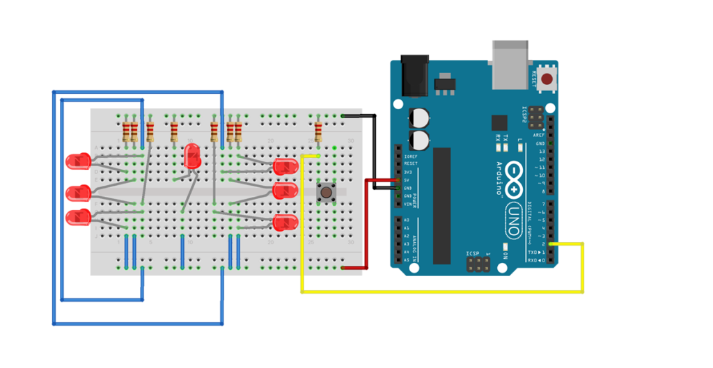
With a bit of perseverance you can assemble 7 LED following the above schema to create a LED pattern that can show one of the 6 dice eye combinations. Each LED is connected in exactly the same way as shown in step 1, but it takes a bit of fiddling to ensure wires do not cross.
| Download the supporting material for step 4 in PDF |
5 – (digitally) Throwing the Dice

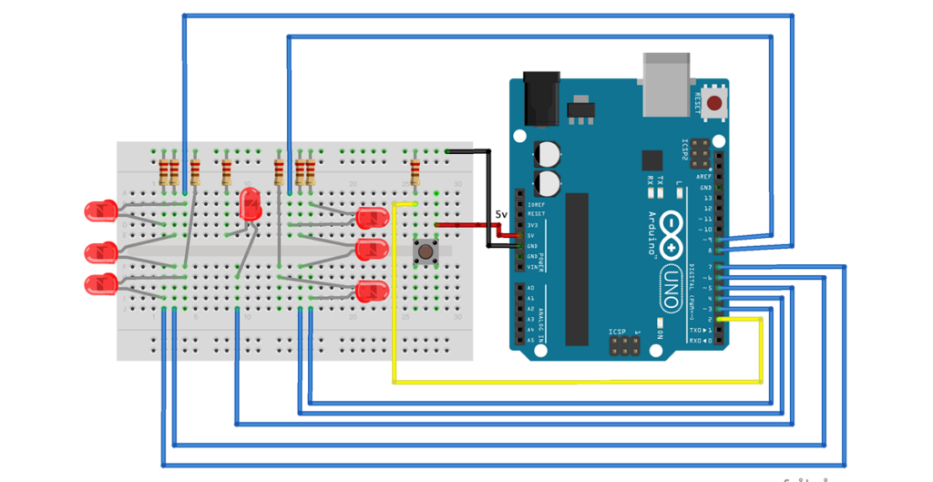
Next step is to put in the code to get a random number between 1 and 6, and show it accordingly by turning the corresponding LED on. I am aware that the code is extremely basic, and that there are much smarter ways to achieve the same (e.g. here), but that is in part on purpose to make it accessible to a wide audience.
/*
Arduino Dice - step 3: A dice made from seven LED + one BUTTON
 Created 27 Mar 2022
 By Fred Voorhorst
 See: www.educati.ch

 This example code is in the public domain.
*/

int BUTTON = 2;
int LED1 = 3;
int LED2 = 4;
int LED3 = 5;
int LED4 = 6;
int LED5 = 7;
int LED6 = 8;
int LED7 = 9;

#define DEBUG 1

void setAllLED(int value) {
  digitalWrite(LED1, value);
  digitalWrite(LED2, value);
  digitalWrite(LED3, value);
  digitalWrite(LED4, value);
  digitalWrite(LED5, value);
  digitalWrite(LED6, value);
  digitalWrite(LED7, value);
}


int throwDice() {
  // get a random number in the range [1,6]
  int randNumber = random(1,7);

  return randNumber;
}

void showNumber(int eyes){

  #ifdef DEBUG
  Serial.print("eyes: ");
  #endif

  if(eyes == 1) {
  digitalWrite(LED4, HIGH);
  #ifdef DEBUG
  Serial.println(eyes);
  #endif
  }
  else if (eyes == 2) {
  digitalWrite(LED3, HIGH);
  digitalWrite(LED5, HIGH);
  #ifdef DEBUG
  Serial.println(eyes);
  #endif
  }
  else if (eyes == 3) {
  digitalWrite(LED1, HIGH);
  digitalWrite(LED4, HIGH);
  digitalWrite(LED7, HIGH);
  #ifdef DEBUG
  Serial.println(eyes);
  #endif
  }
  else if (eyes == 4) {
  digitalWrite(LED1, HIGH);
  digitalWrite(LED3, HIGH);
  digitalWrite(LED5, HIGH);
  digitalWrite(LED7, HIGH);
  #ifdef DEBUG
  Serial.println(eyes);
  #endif
  }
  else if (eyes == 5) {
  digitalWrite(LED1, HIGH);
  digitalWrite(LED3, HIGH);
  digitalWrite(LED4, HIGH);
  digitalWrite(LED5, HIGH);
  digitalWrite(LED7, HIGH);
  #ifdef DEBUG
  Serial.println(eyes);
  #endif
  }
  else if (eyes == 6) {
  digitalWrite(LED1, HIGH);
  digitalWrite(LED2, HIGH);
  digitalWrite(LED3, HIGH);
  digitalWrite(LED5, HIGH);
  digitalWrite(LED6, HIGH);
  digitalWrite(LED7, HIGH);
  #ifdef DEBUG
  Serial.println(eyes);
  #endif
  };
}

void setup() {
  // put your setup code here, to run once:
  // set all LED pins to OUTPUT
  pinMode(LED1, OUTPUT);
  pinMode(LED2, OUTPUT);
  pinMode(LED3, OUTPUT);
  pinMode(LED4, OUTPUT);
  pinMode(LED5, OUTPUT);
  pinMode(LED6, OUTPUT);
  pinMode(LED7, OUTPUT);

  // set buttin pin to INPUT
  pinMode(BUTTON, INPUT);

  // initialize random seed by noise from analog pin 0 (should be unconnected)
  randomSeed(analogRead(0));

  // if we're debugging, connect to serial
  #ifdef DEBUG
    Serial.begin(9600);
  #endif

  //Show all leds work
  for(int i=1; i<=6; i++) {
  showNumber(i);
  delay(500);
  setAllLED(LOW);
  delay(300);
  }
}


void loop() {
  // put your main code here, to run repeatedly:
 int p = digitalRead(BUTTON);

 if (p == HIGH) {

  setAllLED(LOW);
  delay(100);
  setAllLED(HIGH);
  delay(100);
  setAllLED(LOW);
  delay(100);
  setAllLED(HIGH);
  delay(100);
  setAllLED(LOW);
  delay(100);
  setAllLED(HIGH);
  delay(100);
  setAllLED(LOW);
  delay(300);

  int thrownNumber = throwDice();
  showNumber(thrownNumber);
  delay(1000);
  setAllLED(LOW);
 }

}
| Download the supporting material for step 5 in PDF |
Feedback
Any comments or questions, reach out via twitter or LinkedIn
Note: this tutorial was developed to support a short workshop at a local school. Apart from preparing this tutorial, I also prepared an Aruino kit, and still have 10 available as free give-away. Contact me for more info.